![]()
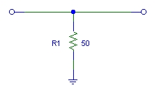
Terminators |
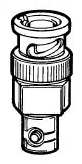
These are usually just a resistor to ground. When a 50W terminator is placed at the end of a 50W coaxial cable, any signal coming down the cable is totally absorbed (ideally) and there are no reflections. Actually, there sometimes are reflections but placing terminators at both ends of the signal cable can help to reduce their effects. The feedthrough type (as shown in the picture) are nice because one end can be connected to an oscilloscope and the other to the coaxial signal cable. Note that because the resistor is usually only rated for ~1/4 Watt, there is a limit to how much DC voltage or pulsed power can be applied without burnout. These can be checked simply by measuring resistance between inner and outer conductors (should be e.g. 50W at both ends).
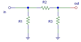
Attenuators |
These are usually placed between the end of the signal cable and the terminator (you must use a terminator to get the labeled attenuation). The resistor values are derived by:
R1 = R3
R1 = Z0*(1+2/(k-1))
R2 = (Z0/2)*(k-1/k)
Where Z0 is the cable/terminator impedance (e.g. 50W) and k is the attenuation factor (ratio of output voltage to input voltage). Note that the attenuation is often given in dB. The relationship between k and dB is
20 log10 k = Voltage attenuation in dB
Values for usual attenuations with Z0 = 50W are as follows:
k |
dB |
R1 |
R2 |
| 2 | 6 | 150 | 37.5 |
| 5 | 14 | 75 | 120 |
| 10 | 20 | 61.1 | 247.5 |
| 100 | 40 | 51 | 2500 |
Attenuators are also often damaged by too much power. These can be checked by measuring resistance between inner conductors on either end. The resistance should be 2*R1*R2/(2*R1+R2) as given in the following table:
k |
dB |
Rcheck |
| 2 | 6 | 33.3 |
| 5 | 14 | 66.7 |
| 10 | 20 | 81.8 |
| 100 | 40 | 98.0 |
Any large variation between the table value and the measured value probably indicates a bad resistor internally.
Notes:
|